

More Guest Blogs


Editor’s note: This is one in a series of blogs detailing the construction of a net-zero energy house in Point Roberts, Washington, by an owner-builder with relatively little building experience. A list of Matt Bath’s GBA articles can be found at the bottom of this page. You’ll find Matt Bath’s full blog, Saving Sustainably, here. If you want to follow project costs, you can keep an eye on a budget worksheet here.
Now that the frame of the house is complete and safe from the elements, I have some flexibility on what to do next. I could, for instance, decide to finish the exterior of the house, put the shingles on, run electrical wire, or install the ductwork. There really isn’t anything to hold me back from working on any of those things.
I decided that the most intelligent thing to do would be to finish installing the roofing as soon as possible whenever I had some decent weather, and when it was too wet to be on the roof I will work on the plumbing. The drain, waste, and vent (DWV) system really needs to be done first because there are three vent pipes that will penetrate the roof, so I want to have those installed before putting the shingles on. The only other roof penetration will be the Soladeck for the solar array electrical connection.
The DWV is one of two systems that make up the plumbing of the house, the other one being the water supply system. The job of the DWV system is to remove water from any plumbing fixtures in the house (drain), transport it to the septic system (waste), and ensure that air pressure doesn’t interfere with the process (vent).
Most people have a pretty good sense of how the first two parts work but are completely oblivious to the operation of the last one. An easy way to explain it is to think back to when you were a kid playing with a drinking straw. You could fill the straw with water, hold a finger over one end of the straw, and the water would magically defy gravity. The venting part of the DWV system is the equivalent of removing your finger from the end of the straw to allow the water to slide out.
Without it, all of the pipes installed to drain and waste would be completely ineffective. In fact, best practices allow for each individual fixture to have a vent of its own. Some of these vents are eventually combined together until they exit out of the roof.
Start with the building code
There is quite a bit of planning that goes into installing a DWV system, but all of the rules are clearly spelled out in the building code. Washington State uses the Uniform Plumbing Code (UPC), whereas other areas may use the International Residential Code (IRC).
Planning starts with deciding on the number and type of plumbing fixtures you will have in your house. Next, you will use the tables in the code to figure out what size pipes to use for the drains and vents. The code dictates minimum pipe sizes and applies a number to each fixture called a “drainage fixture unit value” or DFU. That becomes important when you decide to combine drains or vents.
The system would be pretty inefficient if every single fixture had its own independent drain and vent, all running separately into the sewer or septic. The code allows you to use larger pipe sizes than the minimums and combine smaller pipes into bigger ones as long as the total DFU in the pipe is below the maximum allowed for that particular pipe size.
Additionally, each fixture must have a trap, and the codes spell out what size trap must be used for each fixture. A trap is the U-shaped part of the pipe you may have seen under your sink, and it’s a monumentally important part of the DWV system. Without a trap, noxious fumes from the sewer or septic tank would be free to travel directly into your home. Water in the trap prevents those fumes from entering the house.
Armed with this knowledge, you are now prepared to grab a piece of paper and a pencil (or a computer with CAD) and plan your very own DWV system. There is no wrong way to do it as long as you stay within the rules. But if you are wise about things you may be able to dramatically reduce the amount of piping you need to buy and install. The best practice is to design the system before the framing has been started so that you can plumb in any hard-to-reach areas, as I did before installing the subfloor.
Remember to include a slope
Installing the plumbing is a relatively simple process that involves drilling holes in studs and joists, cutting the pipe to fit, and cementing the fittings to the pipe. The key is to always remember the old plumbing sage’s advice: “Don’t be a dope, slope.” Every drainpipe must be angled so that it descends towards the septic (or sewer) at the rate of 1/4 inch for every foot of pipe.
Vent pipes, on the other hand, should be installed level, or with only a very slight slope toward the drain. Flexible metal straps must be used to attach the pipes to the framing at least every 4 feet on a horizontal run. This will ensure that the slope is maintained even if the pipes get jostled in any way.
I had already installed the drains for the first floor way back, before I poured the concrete slab on which the house is built. Furthermore, I had installed all of the vents and drains that ran through the load-bearing wall when I laid down the subfloor.
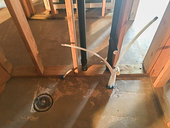
This left very little plumbing to complete on the first story – basically just the stub-outs and vents for the kitchen and bathroom sinks, and excavation of the tub and toilet drains.
Sink stub-outs are typically placed 19 inches above the floor level. I attached a test cap to the end of each stub-out, and once the entire DWV system has been installed I’ll fill all of the pipes with water to make sure I don’t have any leaks.
If the water test is successful, I will cut off the test caps and install the traps for the sinks. After the stub-outs, the pipe continues as a vent up to the second story.
Uncovering drains for tub and toilet
One of the last things I did before pouring the slab was to place a cardboard box around the trap for the bathtub and fill it with gravel. A thin layer of concrete had been skimmed over the top so the box was now completely invisible. I took a sledgehammer lightly to the spot where I knew the outer edges of the box were, and it cracked away pretty easily. Once the thin layer of concrete was removed, I was able to scoop out the rocks and uncover the trap.
I was pleased to see that it was exactly 15 1/2 inches from the wall, which placed it right in the center of the tub. Later, I will use some leveling compound to ensure the area below the tub is perfectly level, and then connect the trap to a tailpiece that will link the drain and the overflow for the tub.
Likewise, a thin film of concrete covered the drain for the toilet (also called a closet bend). I had to chip it away so that I could align the metal ring correctly. In the photo below, you may be able to spot two mistakes I made during the concrete pour. The water supply for the toilet should come up inside the wall, but perhaps I didn’t secure it well enough and it got jostled during the pour. I will end up just plumbing it up out of the floor instead of out of the wall which is the standard practice.
The other mistake is that the toilet flange is supposed to sit up 1/4 inch or so above the concrete so that after the tile is set in place it is sitting on the tile. I will most likely have to cut it off, go out and buy a new one, and reattach it. If I leave it as is, the connection between the toilet and the flange will need to be filled with an extra wax ring or a spacer. Both methods are widely used but neither is as safe as just installing the flange at the correct height. When it comes to the possibility of dirty toilet water leaking, you can never be too safe!
Drain lines installed between the joists
For the second story, the drain lines run between the floor joists just under the subfloor. I drilled holes in the top plates of the first story walls and then installed the horizontal drains between the joists. There was just enough space to ensure they were adequately sloped.
The photo below shows the stub-out for the washer and dryer. You will notice there are two drains, one for the washer and one for the ventless dryer. Instead of venting the moist, hot air to the outside, as would be the case with a conventional dryer, this one will keep the heat in the house. The water drains out, just like the washer water.
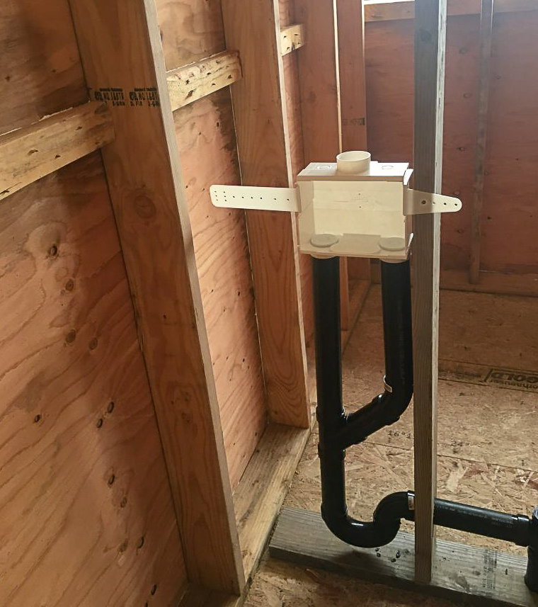
In addition, there were stubouts for the shower, two sinks, and another toilet. The closet bend for the second story is screwed down to the subfloor once it has been aligned in just the same fashion as the one on the first floor.
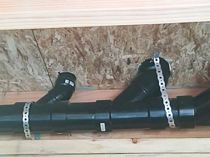
After the stubouts, the vents continue up through the walls and connect above the bottom chord of the trusses. To satisfy building code, at least three of the vents must continue through the roof.
Through the roof
The whole point of working on the plumbing first was to make it easier to install the shingles. I used interlocking aluminum shingles due to their proven record of longevity and their ability to stand up to the high winds and salty air of Point Roberts. As an added benefit, the shingles are made from 95% recycled material, and they reflect heat back into the building rather than absorb it like most roofs.
One of the few downsides is that because the shingles interlock, the only way to adjust one of the shingles in the middle of the roof is to start removing them from the top corner and continue removing them until you get to the one you want to adjust. Obviously that wasn’t something I wanted to take a chance on having to do, and if I tried to just drill through the singles after they were installed they would get bent.
The best approach was to complete the DWV system and install the vents through the roof before installing the shingles.
According to building code, plumbing vents must extend a minimum of 6 inches above the roof. Due to the slope of the roof, an oval shape must be cut out to accommodate the round pipe. Once the three vent pipes were brought through the roof, I glued test caps onto the two lower vents but left the highest one open. This completed the DWV system so that every single outlet was capped and sealed.
Now it was time to test for leaks. I dragged a hose up to the uncapped vent and filled it up all the way to the top to ensure the entire system was filled. Then I turned a full water bottle upside down and placed it over the top. This gave me a reference to look at to check for leaks. If I could no longer see the water in the bottle, then there obviously would be a leak somewhere.
Fortunately, I had done an adequate job of cementing all the ABS together and there were no leaks. The test caps will remain in place until the water supply system has been installed and tested, at which point I will be ready to have the building inspector come by to check everything.
The only other roof penetration will be for the electrical connections to the rooftop solar array. I will be using a Soladeck to both protect the roof opening as a flashing and house the electrical connections all in one. The Soladeck can be positioned pretty much anywhere. I decided the best spot would be near the top of the solar array at the center of the roof ridge. The key was to position it so several of the screws would attach to one of the trusses, which will provide a much stronger connection than just attaching it to the roof sheathing. With all of the roof penetrations complete, I was ready to install the shingles.
Weekly Newsletter
Get building science and energy efficiency advice, plus special offers, in your inbox.


11 Comments
Vents require the same slope as the drains, because if they ever fill up with liquid (back-up condition, or leak testing), they need to drain out. Having them level is unacceptable, because everything has a tolerance, and "level" might actually be ever so slightly sloped in the wrong direction. There may be a difference between particular plumbing codes, but I'd be very surprised if the UPC differs on this point, as it's just common sense.
For anyone reading this and planning on DIY their DWV system, I'd also point out that you need to pay special attention to trap lengths. Plan your where your drains and vents are going during the design phase of the house, if possible. It will make life easier later on.
You said,
"To satisfy building code, at least three of the vents must continue through the roof."
Did you mean for your particular house and vent sizes? I don't recall this particular requirement, and it seems oddly specific, especially if you consider it being applied to a small house with only one bathroom. I think the standard method for specifying roof vent penetrations is based on size, and flows from the size and number of individual vents (and by extension, fixtures) being served by the main vent.
- There are times when you are faced with the choice as to which tasks to do next. The best approach is usually to stick to the accepted sequence of building, which has evolved to minimize conflict between the work of each trade. Plumbing gets roughed in before electrical, because the route pipes take is less flexible than that of wires. Both get roughed-in before the exterior is finished so that hose-bibs and exterior outlets aren't installed renovation style.
- The usual way to rough-in a toilet drain on a concrete floor is to stub-up the pipe and cap it. Once the pour is complete the pipe is cut flush with the slab and the flange is installed. This avoids guessing and mess.
- Pex waterlines passing through the slab should be sleeved to avoid mechanical damage.
- The problem with stubbing out waterlines through the floor, and drains through the wall behind, is you end up having to cut large holes in the back of the vanity to get it into place.
- The UPC requires vents to slope toward the fixture.
Trevor makes a very important point. "Vents require the same slope as the drains, because if they ever fill up with liquid (back-up condition, or leak testing), they need to drain out."
More than once I have cut into existing plumbing vent pipes on building projects and they are full of condensation because they were not sloped properly. I have also seen test caps left in place on plumbing vents going through the roof.
Do vent stacks always have to go through the roof? Could they exit through an exterior wall?
Ours code doesn't allow it but yours may. As I recall the UPC allows it with various restrictions (must be so far above windows and doors, not under a vented soffit etc.), but the IRC doesn't - or wants at least one stack through the roof.
Should mention air admittance valves (as a vent alternative).
That's another thing our code preludes except in very specific cases, but I think some of your's allow them to be used for the whole house.
3 roof penetrations for a 1500 sq ft house with 2 bedrooms and 2 bathrooms is not good planning or design. I have a five bedroom 4 bathroom home with over 4000 sq ft and it only has two roof penetrations...Every hole in the roof is a leak waiting to happen.
Thank you, I'm about to pour a slab and have to consider a ventless dryer. Can you share which one you plan to use?
I'm trying to figure out the details for a tub drain/p-trap in a basement slab. I was thinking about using an Oatey tub box, but am not sure how. It seems that maybe I'm supposed to lay it "upside down" and then cut out the "bottom" after the concrete is poured.
What about the hole in the slab to the stone below? I would have some concern about moisture and radon. Any recommendations? Should/can I seal it up below the plumbing somehow?
Dustin,
You can box out the hole with PT lumber, foam, a cut down 5 gallon bucket, a plastic storage bin, or something like an Oatey tub box. The vapour barrier below the slab gets carried underneath the box and sealed at the pipe. Before the pour temporarily fill the box with sand or gravel so it doesn't move or get concrete in it. No reason to lay the Oatey box upside-down or cut the bottom out, the drain will be entering the box from the side through a hole you make.
Log in or create an account to post a comment.
Sign up Log in